|
|
|
Excessive Brake Servo Movement
Why is a brake servo support bracket necessary?
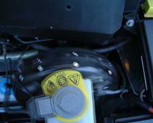
The braking system on the MGF is typical in modern cars in that the braking effort is assisted via the action of a 'brake servo'- basically a hydraulic piston whose action is aided by the vacuum created by the engine. In the case of the MGF, the servo is mounted on the opposite side to the driver for reasons of crash safety. Therefore, when the brake pedal is depressed, the linear motion of the brake pedal depression is translated into a rotational force- and transferred across the width of the car via a torque tube to the brake servo, wherein this rotational force is translated into a hydraulic force that operates the brake callipers to clamp the brake discs.
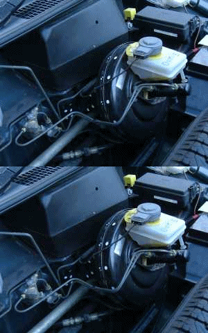
For purposes of a solid pedal feel and efficient brakes, all the braking components should be solidly mounted: the components should NOT move relative to one another. If this occurs, some of the force the driver applies to the brake pedal is lost into movement of the components of the braking system relative to one another. Unfortunately, it appears that this is the case on the MGF. Whilst the brake servo is mounted onto the front bulkhead, some amount of movement is observable when the brake pedal is depressed (and shown graphically below). In fact, a considerable proportion of the observed motion appears upon initial brake pedal depression- and thus probably contributes to some 'sponginess' in the brake pedal feel. Moreover, since more movement of the servo is also observed during maximum effort, it could therefore be limiting maximum braking force; a potential safety point. Overall, the movement of the brake servo (which may be proportional to the age of the vehicle and metal 'fatigue') leads to a disappointingly un-linear brake feel and sponginess that is best eradicated.
 |
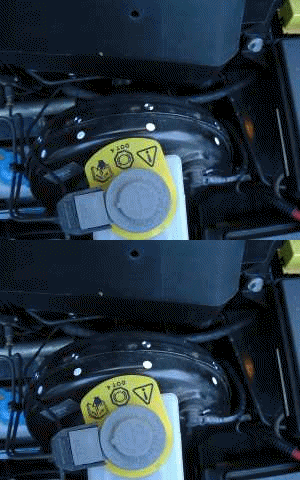 |
| Brake servo: side view.Servo deflection (to the right) is at maximum on brake depression. | Brake servo: top view.Servo deflection (forward) appears to be pivoting about an axis to the right of the servo. |
How Much Movement?
 |
 |
 |
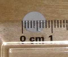
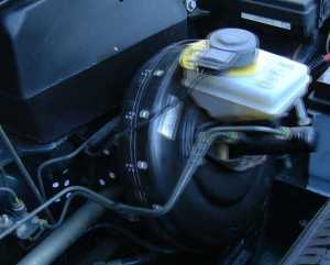
| Picture scale: each circular white dot is 8mm in diameter. | Side view of servo: two pictures super-imposed. From this image we can see that the white dots are only just over-lapping one another in the two images, suggesting up to 6 mm of movement at the right edge of the servo (viewed from driver's seat). | Top view of servo: two pictures super-imposed. From this angle we see again that the white dots have practically separated to the right edge of the servo, yet barely moving at all on the left. |
On the basis of the pictorial evidence shown above, taken from a 6 year old, 60,000 mile MGF, that the movement may be up to 8 mm or more at the right sided edge of the servo (as viewed from the driver's seat). This movement is more than sufficient to imbue a rather mushy feel to the brakes.
What is the solution?
As the title of the page suggests, this involves the installation of a 'servo support bracket' (available from Brown and Gammons, part number BGF0115). This mounts to the right side of the existing servo support bracket and limits the rotational movement we see in the brake servo/master cylinder. Unfortunately, no instructions are supplied with the kit. However, here is how Paul in Preston fitted the bracket to his car:
|
| Brown and Gammon's brake servo bracket BGF0115. Bracket supplied with Allen-headed bolts and nyloc nuts (seen here threaded through the bracket where it mounts to the existing servo mounting bracket. |
Instructions for fitting the Brake Servo Support Bracket to a right hand drive car.
| Tools required: | Socket set with 10 mm and 13 mm sockets 8 mm ring spanner Philips head screw driver |
| Materials suggested: | 30 x 60 mm steel plate; drill two 10 mm
holes 26 mm apart Automotive silicone sealant/ gasket compound |
| Time required: | 1 - 2 hours |
| Notes: | Reasonably straightforward job; biggest problem I had was with the alignment of the servo with its bracket once the screws were removed- even after removing one bolt at a time in an attempt to prevent this from happening, as Paul suggested. Eventually I resorted to using the car jack to reposition the servo to gain alignment- a job that caused some cursing! |
| 1. | Open bonnet, remove black plastic cowl from in front of scuttle area. The cowl is held in place by two bolts on the drivers side and a screw fastener on the passenger side, and two bolts along the lower edge near the spare wheel (these may be missing on your car). | |
| 2. | Enter passenger side of car. Remove glove box by removing four screws, two at the top edge of the box when door is open and two along its lower edge. (note where box sits above metal support on lower edge for later re-installation). Pull off electrical connections to glovebox (click here for more details). Once glove box is removed pull out the heater air ducting where this connects into the central heater and the upper window de-mist vent. This duct just snaps in place and you may have to pull quiet hard, you it wont break if you pull evenly. Next, remove the curved outside air pipe between the scuttle heater box (just below the window) and the heater itself, this is taken out by removing the one obvious bolt to the left of the upper end of the pipe, again this pipe just push fits together, no lower fastener to the heater at all. | 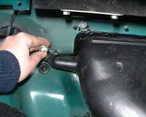 |
| 3. | The bracket fits on the inboard (washer bottle side) of the existing mounting for the brake servo. The wide end of the bracket fits onto the existing mounting, the narrow end onto the bulkhead of the car. There are two holes in either end. | 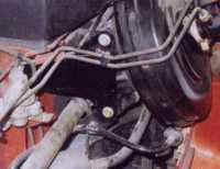 |
| 4. | Bolt the wide end of the bracket to the existing brake servo mounting. The best way to describe where to bolt it to it to say that there is only one obvious place and it's the two bolts on the side of the existing mounting facing inboard which connect the two existing parts of the mounting together. If you remove both bolts at once, the existing mounting springs apart and it is difficult to reinstall the bolts with the new bracket. Therefore, remove the bottom bolt first [it screws into a captive nut which stays in place- 13 mm socket for this job, you'll find a socket extension useful - Rob], then reinstall loosely this bolt at this time the bottom hole of the new support bracket. Remove the top bolt (again captive nut) and then reinstall with the new bracket. Tighten both bolts [I still had problems with bracket and servo alignment- so be careful not to cross-thread the bolts- Rob]. Once the top bolts are tight the narrow end of the support bracket will press lightly against the bulk head. | |
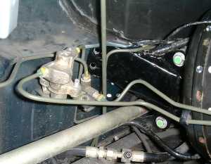
| 5. | In front of the bracket will be an alloy connector in the brake pipes (may be a brake balancer, not sure). Remove the small bolts [8 mm ring spanner will do the job - Rob] which hold this connector to a bracket projecting from the bulkhead. Next, remove any of the black plastic clips which hold together in groups the brake pipes within 300 mm of the new bracket, there are about four clips. The brake pipes around the new bracket can now be carefully moved aside sufficiently to drill the required holes through the bulkhead. | |
| 6. | Drill two 8mm holes
thought the bulkhead, drilling through the existing holes in the narrow end of the new
support bracket. I didn’t use pilot holes as I couldn’t get the chuck of my
drill near enough with the shorter drill bit because of the brake pipes. I used a Black
and Decker bullet point 8mm drill bit, which went through the bulkhead in 10 seconds, I
would recommend this type of bit for this job. Inside the car the holes come though at a
reasonably easy point to get to, there isn’t anything on the inside where the holes
are (once the bits mentioned above have been removed). [An area of potential problem I noticed here was a rigid brake pipe that runs over the top of the bracket to the left hand side of the car. This actually touched the bracket on my car, so I bent the pipe on my car so as to clear the bracket, and not rub and potentially perforate the pipe- Rob] |
 |
| 7. | I made up a doubler plate for the inside of the bulkhead using a double thickness of some painted 1mm sheet steel that I had previously purchased from from the DIY store, B&Q. The plates were 56mm long and 28mm wide with two 8 mm holes drilled centrally [I used 10 mm holes - Rob] to match the required spacing from the new bracket [hole centre spacing is 26 mm- Rob]. Medium size washers may have been ok here. | 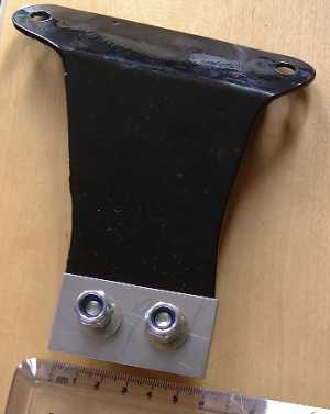 |
| 8. | Install the supplied
bolts and washers through the bracket and bulkhead from under the bonnet. Install the
doubler plate and washers on the inside and screw on the nuts. Put some silicon sealant on
the inside of the doubler plate before it goes on to squash out to form a seal at the
bulkhead. The bolts I was supplied with had round heads and were tightened using a hex
Allen key, however I got someone to just hold the Allen key steady on the outside while I
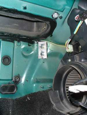
tightened up the two nyloc nuts on the inside with a socket. [I used the stuff pictured right - Rob] |
 |
| 9. | Reattach the brake coupler, brake pipe clips, outside air pipe, heater ducting (just pushes in but be careful its pushed in square), glovebox (including electrical connections) and under-bonnet cowl. | |
| 10. | There is now no distortion at all of the mounting for the servo, the vacuum housing itself distorts a little but the total lost movement has been cut by about 90%. | 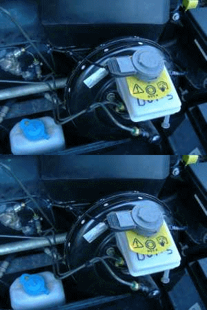 |
Does it work?
| Before | After |
 |
 |
The pictures do speak for themselves here- whilst some movement can still be seen at the servo (which can still be felt, to be brutally honest)- it has been radically reduced. Pedal travel I would guess has been cut by about 30% (sadly I did not measure before and after movement). The pedal feels significantly firmer. On road impressions were extremely favourable- the pedal feels significantly more linear, and therefore easier to modulate brake pressure. Feel through the pedal is better too, and sponginess almost erradicated.
In conclusion, I'd recommend this modification- even if you don't feel that your car has a problem!